soxs_mflat ∞
The purpose of the soxs_mflat recipe is to create a single normalised master-flat frame used to correct for non-uniformity in response to light across the detector plain.
Sources of this non-uniformity include varying pixel sensitivities, obstructions in the optical path (e.g. dust or pollen grains), vignetting at the edges of the detector. A flat-frame is ideally an image taken where the illumination is uniform across the light collecting pixels of the detector. This evenly exposed image can be used to identify irregularities in the response in the detector.
Input ∞
| Data Type | Content | Related OB |
|---|---|---|
| FITS images | raw flats frames (exposures with identical exposure time and detectors readout parameters). UV-VIS requires separate sets D-Lamp and QTH-Lamp flats. | SOXS_slt_cal_NIRLampFlat, SOXS_slt_cal_NIRLampFlatAtt, SOXS_slt_cal_VISLampFlat, SOXS_slt_cal_VISLampFlatAtt |
| FITS Image | Master Bias Frame (UV-VIS only) | - |
| FITS Table | order table containing coefficients to the polynomial fits describing the order centre locations. UV-VIS requires separate tables for D-Lamp and QTH-Lamp. |
Parameters ∞
| Parameter | Description | Type | Entry Point | Related Util |
|---|---|---|---|---|
| frame-clipping-sigma | number of σ from the median frame flux beyond which pixel is added to the bad-pixel mask | float | settings file | |
| clipping-iteration-count | number of sigma-clipping iterations to perform when added pixels to the bad-pixel mask | int | settings file | |
| stacked-clipping-sigma | number of σ deviations from the median pixel flux beyond which pixel is excluded from stack | float | settings file | |
| stacked-clipping-iterations | number of σ-clipping iterations to perform before stacking | float | settings file | |
| centre-order-window | the width of the slice to cut along the centre of each order when determining mean exposure level | int | settings file | - |
| slice-length-for-edge-detection | length of image slice to take across orders when detecting edges | int | settings file | |
| slice-width-for-edge-detection | width of image slice to take across orders when detecting edges | int | settings file | |
| min-percentage-threshold-for-edge-detection | minimum value flux can drop to as percentage of central flux and be counted as an order edge | int | settings file | |
| max-percentage-threshold-for-edge-detection | maximum value flux can claim to as percentage of central flux and be counted as an order edge | int | settings file | |
| disp-axis-deg | degree of dispersion axis component of polynomial fit to order edges | int | settings file | |
| order-deg | degree of order component of polynomial fit to order edges | int | settings file | |
| poly-fitting-residual-clipping-sigma | number of σ deviations from the median fit residual beyond which individual data points are removed when iterating towards a fit of order edges | int | settings file | |
| poly-clipping-iteration-limit | number of sigma-clipping iterations to perform before settings on a polynomial fit for the order edges | int | settings file | |
| low-sensitivity-clipping-sigma | number of σ deviations below the median flux of a master-flat frame beyond which a pixel is added to the bad-pixel mask | int | settings file | - |
Method ∞
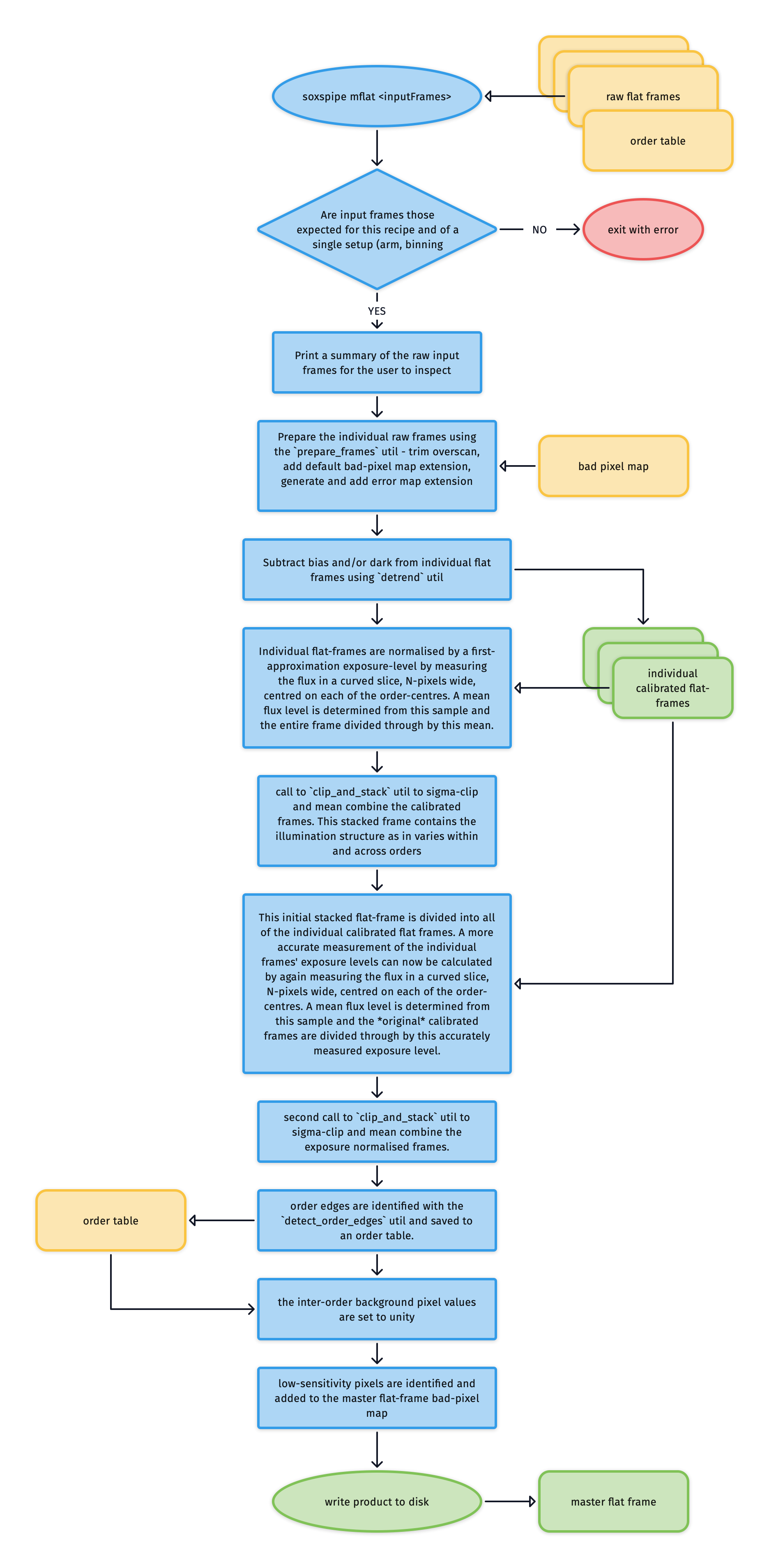
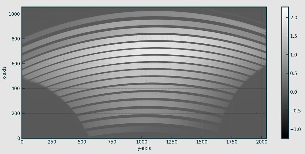
The individual flat field frames need to have bias and dark signatures removed before they are combined. This is achieved with the detrend utility. Here is an example of one such calibrated flat frame:

Normalising Exposure Levels in Individual Flat Frames ∞
Once calibrated, exposure-levels in the individual flat frames need to be normalised as total illumination will vary from frame-to-frame. The individual frame exposure levels are calculated in two stages.
In the first stage the mean inner-order pixel-value across the frame is used as a first approximation of an individual frame’s exposure level. To calculate this mean value, the order locations are used to identify a curved slice N-pixels wide centred on each of the order-centres and bad pixels are masked (see image below). The collected inner order pixel values are then sigma-clipped to excluded out-lying values and a mean value calculated.

Individual frames are then divided through by their mean inner-order pixel value in this first attempt to normalise the exposure-levels of the frames.

The normalised flat-frames are then combined using the clip_and_stack utility into a first-pass master-flat frame:

The second stage then is to divide each original dark and bias subtracted flat frame by this first-pass master flat (see example below). This removes the typical cross-plane illumination and so now the mean inner-order pixel-value across the frame will give a much better estimate of each frame’s intrinsic exposure level.

The mean inner-order pixel-value is calculated again on this frame and the original dark and bias subtracted flat is re-normalised by divided through by this accurate measurement of its intrinsic exposure level.
Building a Final Master-Flat Frame ∞
These re-normalised flats are then combined for a second time into a master-flat frame.

Finally order edges are located with the detect_order_edges utility and the inter-order area pixel value are set to 1.
Low-sensitivity pixels are flagged and added to the bad-pixel map and a final master-flat frame written to file.

UV Master Flat Frame Stitching ∞
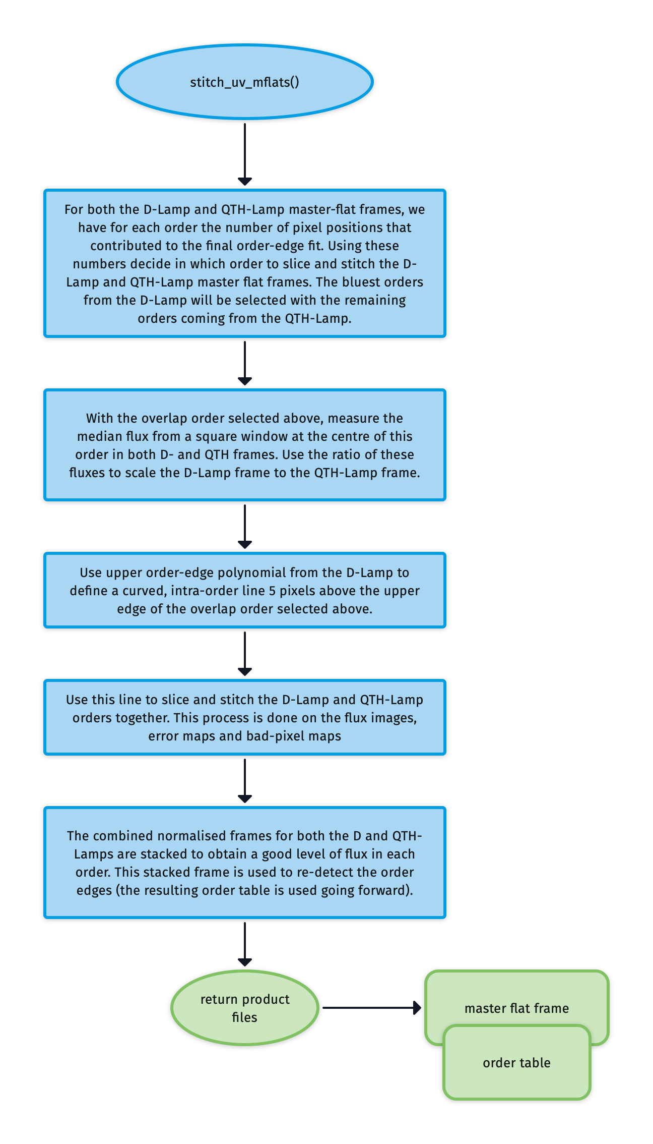
As the UV-VIS uses a combination of D-Lamp and QTH-Lamp flat sets, a further step is required to stitch the best orders from each of these master-flats together into a dual lamp master-flat.
For both the D-Lamp and QTH-Lamp master-flat frames, we have for each order the number of pixel positions that contributed to the final order-edge fit. We use these numbers to decide which orders to slice and stitch from the D-Lamp to the QTH-Lamp master flat frame.
With a crossover order now selected, the median flux from a square window at the centre of this order in both D- and QTH frames is measured. Using the ratio of these fluxes the D-Lamp frame is scaled to the QTH-Lamp frame.
From the upper order-edge polynomial for the D-Lamp we define a curved, intra-order line 5 pixels above the upper edge of the crossover order selected previously. This line is used to slice and stitch the D-Lamp and QTH-Lamp orders together. This process is done on the flux images, error maps and bad-pixel maps. Typically the bluest orders from the D-Lamp will be selected with the remaining orders coming from the QTH-Lamp.
Finally, the combined normalised frames for both the D and QTH-Lamps are stacked to obtain a good level of flux in each order. This stacked frame is used to re-detect the order edges (the resulting order table is used going forward).
Output ∞
| Data Type | Content |
|---|---|
| master flat frame | frame used correct for non-uniformity in response to light across the detector plain (including blaze) |
QC Metrics ∞
| Metric | Description |
|---|---|
| TBC | … |
Recipe API ∞
-
class
soxs_mflat(log, settings=False, inputFrames=[], verbose=False, overwrite=False)[source] ∞ The soxs_mflat recipe
Key Arguments
log– loggersettings– the settings dictionaryinputFrames– input fits frames. Can be a directory, a set-of-files (SOF) file or a list of fits frame paths.verbose– verbose. True or False. Default Falseoverwrite– overwrite the prodcut file if it already exists. Default False
Usage
from soxspipe.recipes import soxs_mflat
recipe = soxs_mflat(
    log=log,
    settings=settings,
    inputFrames=fileList
)
mflatFrame = recipe.produce_product()
Todo
add a tutorial about
soxs_mflatto documentation
-
verify_input_frames()[source] ∞ verify the input frames match those required by the soxs_mflat recipe
If the fits files conform to required input for the recipe everything will pass silently, otherwise an exception will be raised.
-
produce_product()[source] ∞ generate the master flat frames updated order location table (with egde detection)
- Return:
productPath– the path to the master flat frame
-
calibrate_frame_set()[source] ∞ given all of the input data calibrate the frames by subtracting bias and/or dark
- Return:
calibratedFlats– the calibrated frames
-
normalise_flats(inputFlats, orderTablePath, firstPassMasterFlat=False, lamp='')[source] ∞ determine the median exposure for each flat frame and normalise the flux to that level
- Key Arguments:
inputFlats– the input flat field framesorderTablePath– path to the order tablefirstPassMasterFlat– the first pass of the master flat. Default False
- `lamp` -- a lamp tag for QL plots
- Return:
normalisedFrames– the normalised flat-field frames (CCDData array)
-
mask_low_sens_pixels(frame, orderTablePath, returnMedianOrderFlux=False, writeQC=True)[source] ∞ add low-sensitivity pixels to bad-pixel mask
- Key Arguments:
frame– the frame to work onorderTablePath– path to the order tablereturnMedianOrderFlux– return a table of the median order fluxes. Default False.writeQC– add the QCs to the QC table?
- Return:
frame– with BPM updated with low-sensitivity pixelsmedianOrderFluxDF– data-frame of the median order fluxes (ifreturnMedianOrderFluxis True)
-
stitch_uv_mflats(medianOrderFluxDF, orderTablePath)[source] ∞ return a master UV-VIS flat frame after slicing and stitch the UV-VIS D-Lamp and QTH-Lamp flat frames
- Key Arguments:
medianOrderFluxDF– data frame containing median order fluxes for D and QTH framesorderTablePath– the original order table paths from order-centre tracing
- Return:
stitchedFlat– the stitch D and QTH-Lamp master flat frame
Usage:
mflat = self.stitch_uv_mflats(medianOrderFluxDF)
-
find_uvb_overlap_order_and_scale(dcalibratedFlats, qcalibratedFlats)[source] ∞ find uvb order where both lamps produce a similar flux. This is the order at which the 2 lamp flats will be scaled and stitched together
- Key Arguments:
qcalibratedFlats– the QTH lamp calibration flats.dcalibratedFlats– D2 lamp calibration flats
- Return:
order– the order number where the lamp fluxes are similar
Usage:
overlapOrder = self.find_uvb_overlap_order_and_scale(dcalibratedFlats=dcalibratedFlats, qcalibratedFlats=qcalibratedFlats)